Structure identifiers – Standards-compliant and cross-disciplinary structure
A consistent and well thought out structure of plants and equipment using structure identifiers from the outset simplifies and accelerates the development and design process immensely. Complete mechatronic parts lists can be generated fully automatically, and the matching of modules via ERP systems with the data from the mechanical CAD field can be quickly and conveniently accomplished. It is the marriage between electrical and mechanical engineering. The bridge to the electromechanical and thus mechatronic parts list is easy to implement by building small functions and functional units that match the mechanical modules on the one hand, while also being repeatedly usable any number of times on the other.
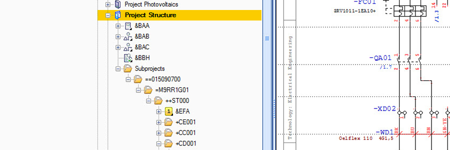
The trick here is thus to essentially reuse modules and their associated electrical subcircuits. For example, if the motor drive as well as the protection and control system of robot #1 from production line #1 in factory A are to be reused in robot #2 of the production line #5 in factory B, you can simply drag and drop the macro of this subcircuit into the plans of the plant at that location. Provided the structure was previously created appropriately, all identifiers stored in the macro will be automatically picked up and inserted into the new structure. This eliminates the time-consuming and error-prone manual renaming process. The new reference designations are uniquely assigned to factory B in all documents, including the parts lists, terminal charts, for procurement or costing, etc., – wherever the components appear.
A previously created structure, in turn, requires you to “have consistently thought this through from the outset”. A little effort at the beginning saves a lot of time later, avoids confusion and increases the transparency and quality of projects. Designers and operators can now identify and determine the location (++) and mounting location (+) as well as the function (==) and plant (=) at any time.
The structure identification is applied to both plants and within plants for specific locations, areas and functions or any categorization and added to a project. The IEC 81346 standard describes the design of a plant as an object model with the three independent aspects: “product”, “function” and “location”. The scope of this standard extends beyond the purely electrical engineering area and describes technical systems in their entirety. Mechanical elements are taken into account just like typical electrical engineering objects. However, the standard does not dictate how to structure a project; it merely serves as a guide for a clear and comprehensible breakdown of a project.
A consistently thought out structure initially follows the parent structure:
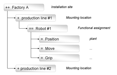
| ++ | For the installation site = location with multiple mounting locations, such as buildings, rooms or premises |
| == | For the functional assignment = the description a parent functional unit such as a robot #1, for example or |
| & | For the type of documents |
For the parent structure, the new Add-On “Advanced Project Structure” of WSCAD SUITE 2017 is required.
In the second step, the child structure follows:
| + | For the mounting location, this may be a cabinet, a ventilation system or the spindle of a milling center, for example |
| = | For the function of a functional unit, it could, for example, be “positioning”, “moving” or “gripping robot #1 from above |
This functionality is part of the WSCAD SUITE and has now been adapted to match the designations used in the IEC 81346 standard
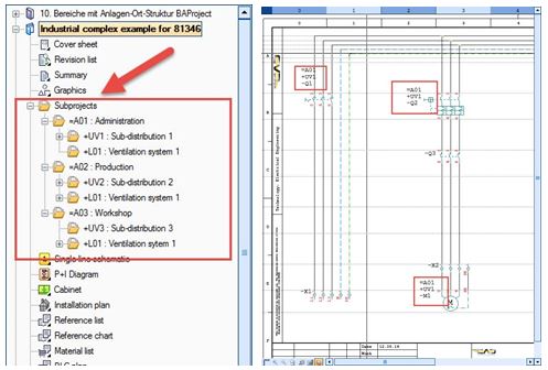
Example of a simple structure
We are planning an industrial complex with production, workshop and administration. In each of these areas, we have power distribution, ventilation and heating and cooling systems. The structuring for this could be as shown in Figure 1:
A distinction is made here between the areas (administration – production – workshop) and the locations (subdistribution ventilation and possibly heating-cooling). Components installed in the control panel would be found in plant 01, subdistribution 1 and would be followed by the designation of the component, e.g., M1. The full reference name key (ref. name key) in this example would therefore be = A01 UV1-M1.
Example of advanced structuring
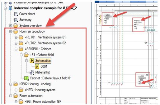
It is, however, also possible to have a more detailed identification of the equipment in the plant as shown in Figure 2.
In this example, the plant is not divided into the different areas of administration – production – workshop, but into the technical aspects of the plant: ventilation system – switchgear – technology center – control panel. In this case, the ventilation system (L001) is assigned the function of the switchgear (SSISP01) and, in addition, the Technology Center 1 (TZ1) is divided into multiple locations which, in the example, is the location Field1 (F1).
Thus, the motor M1 is clearly identified via the function and location aspects. The ref. name (reference name) in this example would be as follows: ==L001=SSISP01++TZ1+F1-M1
The new Advanced Project Structure Add-On at a glance
- Extension of the structure identifiers ‘-‘, ‘+’ and ‘=’ with the aspects ‘==’ (functional assignment), ‘++’ (installation site) and ‘&’ (document type) in accordance with the IEC 81346 and IEC 81346/3 standards
- Display of the KKS (identification system for power plants) and data point keys for Building Automation
- Creation of substructures using “Dot” and “Slash” separators
- Extension of projects to any number of substructures
- Settings options for project structure identifiers: Locked, Descriptive, Available
- Settings options for resource reference designations: Not available, Referencing, Referencing with inheritance, Descriptive, Descriptive with inheritance
The benefits
- Quickly find resources by means of a continuous and systematic structuring of plants and machines – in the plan as well as the physical plant
- Simple reuse of functions, modules and subcircuits
- Sheet-independent identification of resources
- More transparency in complex projects with cross-disciplinary validity
- Production-oriented documentation and unique labeling
- Grouping of parts lists, e.g., from ERP exports
- Easy creation of mechatronic parts lists
- Filtering and sorting criteria for customized exports
- Setup of optimally structured sample projects, defaults and definitions for optimal structures (forms, structure of part data, etc.)
When does it make sense to use the new Advanced Project Structure Add-On?
- For projects exceeding 80 pages in scope
- For those who want to standardize structurally
- For those involved with cross-disciplinary work (Electrical, Fluid, P&ID)
Typical applications are found in plant engineering, the energy industry and the manufacturing of complex machinery.
If you lack the expertise or the time to build an efficient and standards-compliant product or plant structure, we would be happy to assist you. Our consultants have extensive experience in the structuring of machines and plants and can draw on a variety of best practices from the industry. In addition, we are also proficient in multiple E-CAD systems. So just check with us even if you are using some other E-CAD system.

Jürgen Panhölzl
Manager,
Global Business Services