
How can I manually create custom electrical installation symbols in WSCAD?
Creating custom symbols for your schematic design is a straightforward process where you draw basic geometric shapes, convert them into standard symbols, and refine them in the Symbol Editor with functional texts and connection points. This method offers a practical guide for professionally digitizing your own components, ensuring that every element in your Circuit diagrams is precisely positioned, fully functional, and perfectly adapted to your project’s scale.
In this video, we explore the step-by-step journey from a simple drawing to an intelligent symbol:
- From Graphics to Intelligence: Start by drawing a simple rectangle and grouping it with text before using the “Graphic to standard” function to breathe life into your symbol.
- Precision and Orientation: Discover how the Orientation item helps you maintain a sense of scale, even as symbols remain freely scalable during placement.
- Smart Labeling: Learn to insert placeholder function texts that use “Center Center” alignment to ensure professional-looking descriptions every time.
- Keyboard Shortcut Mastery: Speed up your workflow by using Ctrl + D and the Plus key to distribute connection points (pins) perfectly across the grid in seconds.
- Visual Clarity: See how to manage pin properties in the editor to hide numbers and names, keeping your final installation plan clean and easy to read.
While building from scratch offers maximum creative freedom, you can achieve professional results even faster by repurposing your existing library assets. If you already have a foundation in other libraries, a few clicks are all it takes to transform them for new tasks.
On our WSCAD YouTube channel, you’ll find additional short video tutorials and webinar recordings, as well as further useful information about WSCAD and the ELECTRIX electrical CAD.
Is there a shortcut to make single-line symbols usable for electrical installation in WSCAD?
You can significantly speed up your schematic design by converting existing one-pole symbols for use in electrical installations, simply by changing their technology setting within the Symbol Editor. This efficient approach allows you to leverage the Symbol Explorer to reuse proven graphics, ensuring that your Project documentation remains consistent while saving you the time of drawing new symbols from scratch.
This tutorial demonstrates how to expand your installation library in record time:
- The Technology Switch: Open any single-line symbol and change its technology to “Electrical installation” to instantly adapt it for new applications.
- Organized Workflows: Find out how to save these symbols in dedicated EI libraries with clear naming conventions to keep your workspace tidy.
- On-the-Fly Scaling: Master the use of the S and Shift + S keys to adjust the size of your symbols dynamically as you place them into your plan.
- Seamless Data Linking: Assign the reference name from your schematic to your new symbol—the blue eye icon provides immediate visual confirmation of a successful link.
The Symbol Editor acts as a professional workshop: You can either craft a brand-new tool from raw materials (manual creation) or take a proven tool from another department and re-calibrate it for its new purpose (conversion). Both methods ensure you have the perfect equipment to digitize your components and complete your installation project with precision.
This Videos offer a practical guide for creating electrical installation symbols in WSCAD Electrix. The process begins with drawing simple geometric shapes, which are then converted into standardized symbols and functionally enhanced with placeholder texts. A major focus is placed on the precise positioning of connection points, emphasizing the use of keyboard shortcuts for efficient work within the grid. Additionally, the tutorials explain how to adjust the visibility of pin properties to maintain clarity in the circuit diagram. Since the created elements are freely scalable, they can be flexibly adapted to various project sizes. Overall, the materials serve as a step-by-step guide for users looking to professionally digitize their own components.
Two Methods for Symbol Provision
The Videos describe two distinct workflows for providing symbols for electrical installations in Electrix:
- Manual Creation (Method 1): A symbol is built from scratch using graphical shapes, converted into a standard symbol, and then detailed within the Symbol Editor.
- Conversion of Existing Symbols (Method 2): This is a more efficient approach where an existing symbol from the Single Line (one-pole) library is modified in the Symbol Editor for use in electrical installations.
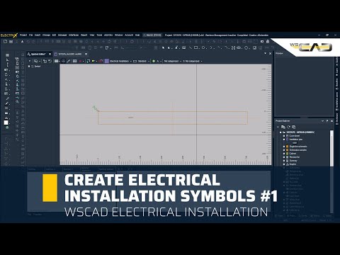
Method 1: Manual Creation via the Symbol Editor
- Graphical Basis: Draw a rectangle and insert any standard text.
- Conversion: Group the elements using “Graphic selection” and convert them into a symbol via the “Graphic to standard”
- Refinement in the Symbol Editor: Open the Symbol Editor by right-clicking the symbol and activate the “Orientation item” to help with positioning.
- Functional Texts: Delete the standard text and add a “Placeholder function text” with “Center Center” alignment.
- Pin Configuration: Add connection points (Pins) using the circle type for better recognition.
- Efficiency Shortcuts: Align the first pin on the grid and use Ctrl + D (duplicate), arrow keys, and the Plus key to distribute further pins quickly.
- Optimizing Visibility: In the Pins tab of the Symbol Editor, select all pins and set the visibility of pin numbers and names to “No”.
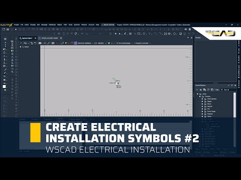
Method 2: Converting Existing Symbols (Single Line to EI)
- Symbol Selection: Choose a symbol from the Single Line symbol library.
- Technology Change: Open the Symbol Editor and change the “Technology” setting from “Electrical engineering one pole” to “Electrical installation”.
- Library Management: Save the symbol in an EI Library (e.g., using the suffix “EI” for clarity).
- Placement and Scaling: Insert the symbol into the installation schematic and adjust its size using the S or Shift + S
- Data Linking: Assign the reference name of the corresponding part from the schematic; a blue eye icon will indicate a successful link.
Haven’t tried ELECTRIX AI yet?
Try ELECTRIX AI, the only AI-powered electrical CAD, completely free and without obligation. Experience the full “Ultimate” version with all modules and add-ons. With integrated Artificial Intelligence, you’ll work more efficiently and productively, save time and money, and reduce errors. Enjoy less stress and deadline pressure while effectively addressing the skilled labour shortage.