In WSCAD ELECTRIX 2021, the Design Engine (Editor) has been completely redesigned. The Design Engine is the program unit that is responsible for the structure and design of the schematic pages.
This results in many smaller and larger changes when placing and moving objects and when scrolling through documents. In addition, the entire design process has been accelerated and improved. This document summarizes the most important changes.
Drawing area general
- The drawing area is about 5x larger than the selected sheet format. The frame still has its coordinate origin in the lower left corner.
- The document is no longer docked at the top left. The area above the document and left of the sheet can now be used.
- Objects (e.g. symbols, text frames or macros) can be placed partially or completely outside the frame. Elements placed there are also considered in reports, for example. If you like, you can also place a data sheet outside the frame.

- Zooming and panning within the drawing area is much smoother and faster.
- The view bar below the document is now available as a separate toolbar.

Zooming
- The scroll bars for zoomed documents could be dropped. Simply move the contents of a zoomed document with the mouse wheel pressed down, the third mouse button or the Move context menu command of the page. While moving, you can still zoom in and out with the mouse wheel or the F2 and F3 keys. Vertical moving with the mouse wheel is therefore no longer necessary.
- A double click on the mouse wheel (= F4 key) zooms to the whole page.
- The two zoom icons in the view bar no longer cause an immediate zoom in/out. Use the icons to activate the zoom function and click on them to zoom in/out directly to the desired position in the document. This makes it much easier to zoom in on objects than before.
- If some lines (e.g., medium connection lines) appear too thick when zooming, then the lines can be displayed in pixel thickness using the View | Show all lines in pixel thickness main menu command or the checkbox in the properties dialog of the page. I.e., the Fixed checkbox in the property dialog of medium connection lines could be dropped since the line thickness was not zoomed when activating this function.
- In addition, the Show all lines in pixel thickness check box has been added to the following dialogs:
- Properties dialog of the page
- Import wizard for DXF/DWG
- Export wizard for DXF/DWG/PDF/graphics
- Print dialog
Marking
- Objects in the drawing area are already highlighted when you move the mouse pointer over them. This makes it easier to call up the context menu of a text container, for example. If you hover over a symbol, the BMK field is also highlighted. If you only hover over the BMK field, only the BMK field is highlighted.
- Double-clicking on a text container opens directly the properties dialog of the associated symbol.
- To correctly mark an object, it is no longer sufficient to click on a free space within the object, but you must click on a line of the object. When you hover over the object, it is not yet selected.
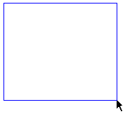
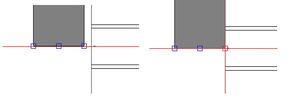
- When drawing a rectangle with pressed left mouse button to mark elements, the frame is displayed in a different color depending on the direction of drawing:
From left to right: blue
The whole symbol must be in the drawing area for the object to be marked. The symbol texts do not have to be in the drawing area.
 From right to left: green
Only a part of the symbol must be in the drawing area for the object to be marked.

 From right to left: green
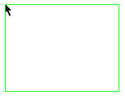
Placing
- Objects can be placed better on a line, because the object is caught by the line, even if the snap is switched off.
- While placing, drawing or moving objects, if the red crosshairs come close to another object, the snap points of this object will be visible and the crosshairs will be attracted by it, even if the snap is switched off. Smaller objects can be selected better this way.
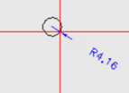
- Innovation in the disciplines CE and EI:
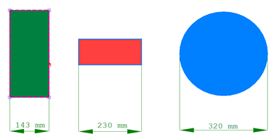
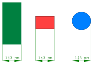
When inserting a circle, the radius outside the circle is displayed. This makes it easier to read the value, especially for small radii. With the Tab key you can enter the value in an input field directly from the keyboard.

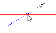
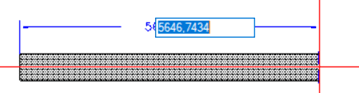
- Innovation in the disciplines CE and EI:
When inserting a polyline (e.g. a polygon), the length of the line is now displayed instead of the distance from the start/end point. The display of the length is more user-friendly than the display of the coordinates. With the Tab key you can enter the value in an input field directly from the keyboard.

- Innovation in the CE discipline:
Cabinet elements (e.g., drill holes or slots) placed inside a parent element (e.g., cabinet control, contactor) can only be moved inside the parent element. This prevents from unintentional placing elements outside the parent element.
Moving
- When moving an object, you no longer need to hold down the mouse button. Clicking again places the object. The object remains visible in its old position until it is placed in the new position.

- Innovation in the disciplines CE and EI:
When moving (or copying) an element on a CE page or EI page, you can use the Tab key to switch to the input fields which display the distances to the original position of the element. You can enter the values directly via keyboard. Use the return key to confirm the entered value. Thus, an exact placement is possible. With another press of the Tab key you can enter the coordinates.
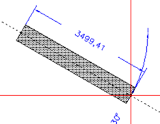
When moving (or copying) an EI symbol, the angle to the original position is also displayed. With the Tab key you can also enter this value directly. - Innovation in the disciplines CE and EI:
When pressing the F9 key while moving, the origin of the coordinates is moved to where the crosshairs are located (e.g. to the beginning of a top-hat rail). Now you can use the Tab key to enter values that are relative to this new coordinate origin. This ensures exact placement here as well.

- Innovation in the CE discipline:
In order to move objects that are placed under a cover, the cover is first switched to transparent with a left click. The objects are then marked with a frame and can be moved with the Shift key and another left click. - If the orthogonal mode is activated, it remains activated even when moving. This allows objects to be moved exactly at right angles. If this is not desired, simply press the F6 key.


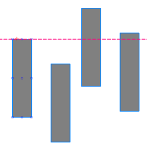
Aligning and Adjusting
- Alignment and adjustment of objects has been improved. It is now much easier to choose the reference object to which the other objects should be aligned and adjusted.
The toolbar Alignment Objects has also been simplified.

After you have marked the objects individually or with a frame in any order, use the red crosshairs to navigate to the edge or axis of the object to which you want to align all other objects.

Aligned at the top edge

If you want to adjust the width, height or size of objects, simply click on the object whose dimensions you want to transfer to the other objects.

Adjusted to the width

- It is easier to position one object to another object. If an object is close to another object, small squares are displayed. If you move the crosshairs into a square, it turns red and you can place the object directly on the other object at this point.

- If center-aligned text does not fit in the frame provided for it, the text is no longer cut off on both sides but displayed left-aligned.3 dots on the right indicate that further text cannot be displayed.
Editing frames
Elements of the frame cannot be edited immediately when you are editing elements in the drawing area. To do this, you must first click with the mouse on the frame or an element in the frame. Now you can edit any element in the frame. If you want to go back, click on an element in the drawing area. A click on an empty place on the page is not enough.
Import/Export of DXF/DWG/PDF
- DXF/DWG files can now be better integrated into the WSCAD software. A conversion to the WSCAD format is no longer necessary for this purpose. When creating a new project page, you can now reference a DXF/DWG file directly in the Create project page(s) dialog using the Based on the DWG page check box. A copy of the DXF/DWG file is automatically saved in the project directory Graphics. The content of this copy is displayed on the project page. Elements can be moved and deleted, and all existing layers are automatically transferred to the WSCAD layer management.
Note: If you replace the copy with another file with the same file name, the contents of this file are displayed in the project page. - An already imported DXF/DWG file can be converted to a referenced DXF/DWG file via the context menu DWG functions | Convert based on DWG.
- The line thickness used in the drawing area for e.g. frames and connections is now better displayed when exporting to DXF/DWG/PDF and when printing. Thus, the specification of a line thickness factor for better visibility of the lines could be omitted.
- If some lines (e.g. medium connection lines or frame lines) appear too thick, the lines can be output in pixel thickness using the Show all lines in pixel thickness check box.
- When exporting referenced DXF/DWG files to PDF, the output quality has been significantly improved.
Discipline EI
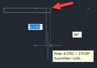
- When creating, moving and rotating walls, doors and windows, you can use the Tab key to open input fields and enter the values directly with the keyboard. You can jump between length/distance, angle and coordinates.

- When rotating elements the length and the angle are displayed. At 0° 30° 45° 60° 90° 120° 135° 150° 180° auxiliary lines appear where the element is caught by the auxiliary line.

- With the two new context menus Finish room directly and Finish room mirrored of a wall chain you can have the still incomplete room finished automatically.
- If one wall segment overlaps the other, the walls are connected.
- The placement of doors and windows outside walls is prevented.
- Doors and windows are “caught” by the wall when inserted into a wall using the magnetic function. Even when moving doors and windows, the magnetic function remains intact.
- The Typlasso function can also be used for walls, doors and windows. If you drag a frame over several elements, only elements of the same type are selected.
- The option to set walls, doors and windows invisible via the properties dialog is not needed and has been removed.
- The key combination Ctrl+M can be used to change the docking point between top, middle and bottom edge when inserting a wall. The inflexion points also depend on the choice of the docking point.
Docking point top edge/right
 Docking point center
 Docking point bottom edge/left
 Docking point center
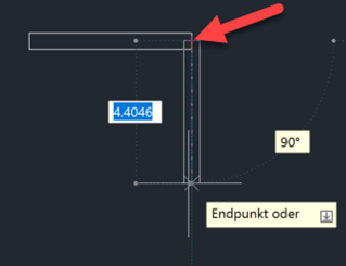 Docking point bottom edge/left
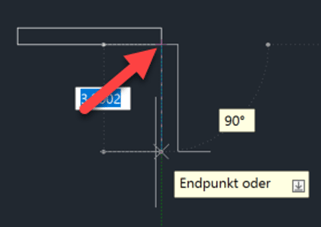
I hope this blog has helped you. You can download this article free of charge.

Thomas Janowicz, Technical Writer
Documentation Management