Using 3D data for cabinet engineering
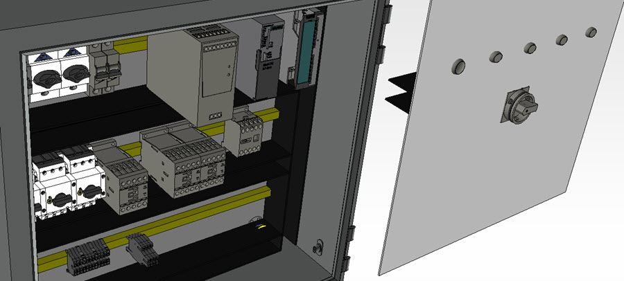
With the WSCAD SUITE, you can display a cabinet designed in the Cabinet Engineering discipline as a 3D model. For this, you need 3D models for the components. WSCAD already provides 3D models for the demo project. You can import additional 3D models from the electrical CAD data portal wsacduniverse.com into the WSCAD SUITE. You then just have to assign the 3D model to the part of the component.
Prerequisite: You need the WSCAD SUITE Cabinet Engineering module in the Expert version for this purpose.
Procedure
- Check if 3D model exists in the WSCAD SUITE
In the 3D view of the cabinet, you can check for which components no 3D models have been assigned to the component’s parts. These components are shown schematically as a cuboid. - Check if 3D model exists in wsacduniverse.com
If the 3D model does not exist in the WSCAD part database, check if the part and 3D model are present in the electrical CAD data portal wsacduniverse.com. - Download 3D model from wsacduniverse.com
Download the 3D model file locally to your PC in a directory of your choice. - Assign 3D model to the part
Assign the 3D model to the part. - Change 3D model
If the 3D model is not aligned correctly, you can define one side as the front side.
Checking if a 3D model exists in the WSCAD SUITE
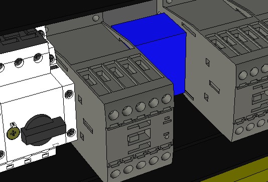
In the 3D view of the cabinet, all components that do not have 3D models in the WSCAD part database are shown as cubes.
1. From the cabinet page, open the 3D view of the cabinet. You have the following options:
- using the keyboard shortcut Ctrl + o.
- via the menu View | Cabinet 3D view.
Note: Components without a 3D model are shown schematically as a cuboid.
2. On the cabinet page, click on the context menu command Properties next to the component.
3. Click on the Customize symbol button in the Part row. The WSCAD part management opens.
Alternative
You can also check in the WSCAD part management whether a 3D model already exists for the part of the component.
1. Click in the main menu of the WSCAD SUITE on Tools | Master data | Part management.
2. Set the 3D Model column to visible:
a) Right-click in any column header.
b) Click Show/hide columns.
c) Activate the 3D Model entry on the Normal tab.
d) Click OK. The 3D Model column is displayed.
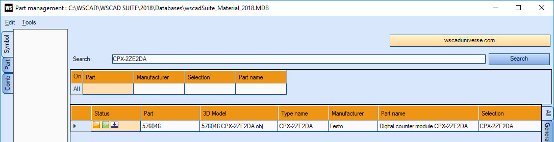
3. Enter the part for which you need a 3D model in the Search field of the part management and click on the Search button.
4. In the 3D Model column, you will see if there is already a 3D model for the part.
Checking if the 3D model exists in wsacduniverse.com
If the part does not exist in the WSCAD part database or if no 3D model is available for the part, you can check if the 3D model is available in the electrical CAD data portal wscaduniverse.com.
1. To log into wscaduniverse.com from within the WSCAD SUITE, you can:
- Click in the WSCAD SUITE main menu on Tools | Master data | Part management and then on the wscaduniverse.com button from there.
- Click in the WSCAD SUITE main menu on View | Additional windows | wscaduniverse.com.
2. If you do not have a user account as yet:
a) Click on the Registration link in the title bar of wscaduniverse.com.
b) Enter your user data.
c) Click on the terms and conditions link and read the terms and conditions.
d) Select the check box I have read the terms and conditions and agree!.
e) Finally, click Now register.
3. If you already have a user account:
a) Enter your email address and password in the two fields.
b) Click Login.
4. The homepage of wscaduniverse.com opens.
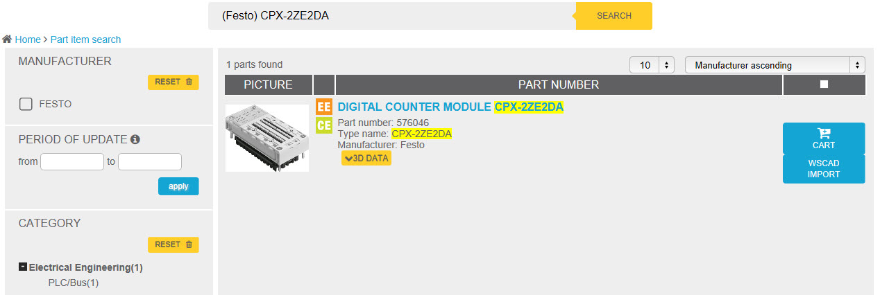
5. In the Search field of wscaduniverse.com, enter the part for which you need a 3D model, e.g., CPX-2ZE2DA from the company Festo, and then click the Search button.
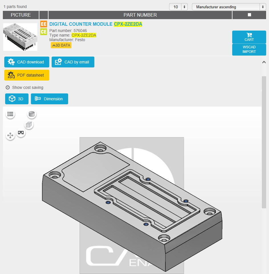
6. The search results are displayed in the part list. If a 3D model exists, the 3D Data button is displayed.
Note: At the moment, 3D models are not yet available for all parts.
Downloading the 3D model from wsacduniverse.com
The 3D data provided in wsacduniverse.com can be downloaded locally to your PC. If the part does not already exist in the WSCAD part database, you can immediately import it into the WSCAD SUITE.
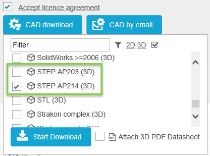
Depending on the part, the following download options are offered:
![]()
You can save the 3D model directly as a STEP file in a directory of your choice.
![]()
You can download the Cadenas 3D model and save it in a directory of your choice.
The following describes the download of Cadenas STEP files.
1. If the part does not already exist in the WSCAD part database, click in the part list on WSCAD Import. The part is imported.
2. Click in the part list on the 3D Data button at the desired part.
3. If you are downloading 3D data for the first time, you need to register with Cadenas:
a) Click on the Accept license agreement link and read the license terms.
b) Then select the Accept license agreement check box in front of the link.
c) Enter your email address in the Email Address field and click on the symbol button at the end of the field
d) Enter your user data and then click OK, You have successfully registered with Cadenas
4. Click on the CAD download button.
5. Select the desired STEP-CAD format.
Note: Both STEP formats offered can be used for the 3D view. The level of detail and color of the 3D models are determined by the creator and are not dependent on the STEP format.
6. Click on the Start Download button. The CAD formats are packed in a ZIP file.
7. Save the ZIP file to your PC.
8. If you want to download more 3D models, repeat the previous steps.
9. Close the wscaduniverse.com window.
10. In Windows Explorer, navigate to the storage location of the downloaded ZIP file and unpack the ZIP file.
Assigning the 3D model to the part
You must assign the downloaded STEP file to the part. A 3D model is created in the form of an obj and an mtl file.
1. Click in the main menu of the WSCAD SUITE on Tools | Master data | Part management.
2. Enter the part for which you downloaded the 3D model in the Search field.
3. Click in a cell of the part and press the F4 key.
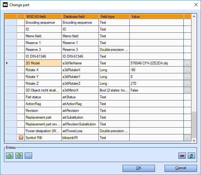
4. Scroll to the WSCAD field 3D Model and click on the Customize symbol button at the end of the row. The 3D Properties dialog opens.
5. Click at the bottom of the 3D Model field on the Customize symbol button.
6. In the Explorer, select the item STEP (*.stp;*.step) in the drop-down list behind the File name field.
7. Navigate to the storage location of the unpacked ZIP file and select the STEP file.
8. The 3D model is automatically created from the STEP file and stored as obj and mtl files in the WSCAD directory “3DObjects”. The 3D model is displayed in the 3D Properties dialog.
Changing the 3D model
In the 3D Properties dialog, you can customize the 3D model if required. For example, the 3D model may not be aligned properly. In that case, you must define a front side.
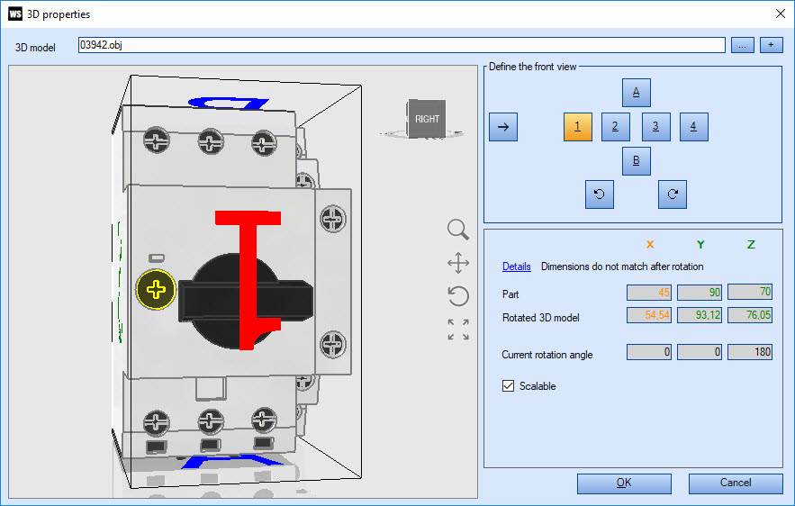
1. Define the front view in the Define the front view area. The view set here is defined as a front view when saving the dialog:
a) You can rotate the component in the 90° grid around the 3 axes via the symbol buttons A, B and 1, 2, 3, 4. Blue-bordered symbol buttons show the front view suggested by the program.
b) You can also rotate the component with the symbol buttons outside the 90° grid and zoom in and out of the component. However, the front view can only be stored without zooming in the 90° grid. Use the right arrow symbol button to jump to the front view closest to your setting in the 90° grid. This view is also saved.
2. If the X, Y and Z axes below the Define the front view area are shown in green, the dimensions resulting from the rotation match the dimensions from the part record. If one or more axes are shown in yellow, the dimensions differ slightly from one another; if they are shown in red, the deviation is considerable. When saving, the component is adapted to the part dimensions.
3. You can display the following dimensions via the Details link:
- Part: Dimensions in mm, which are read from the part record.
- Rotated 3D model: Dimensions in mm resulting from the rotated 3D model.
Note: Clicking the symbol button 1 without setting any rotation angles takes you back to the orientation originally defined for the 3D model. - Current rotation angle: Shows the rotation angles generated by the selected symbol buttons.
4. You may be able to fix presentation problems with the Scalable check box:
- Activated (default): For the 3D view, the dimensions stored in the part are used. This can lead to distortions in round elements.
- Deactivated: For the 3D view, the dimensions stored in the STEP file are used.
5. Finally, click OK.

Thomas Janowicz
Technical Writer,
Documentation Management