Controlling the colors of elements
All elements within schematics and cabinet plans are shown on the screen in color by default. This color information is contained in the elements themselves, but can be changed or overridden as needed by the following options.
This applies not only to symbols, but also to texts, free graphics, lines, cables, etc.
For color control, the following hierarchy applies:
- Changing the colors of elements
You can change the color of individual symbols with the Symbol Editor. For all other elements such as text, free graphics, lines, etc., you can change the color via the properties dialog. - Overriding the colors of elements
You can override the colors for many elements via Tools | Settings (options) | View, e.g., generally for all symbols or for the general text. In that case, all symbols will have the same color. - Color override with the layer function
You can change symbols on a specific Layer and assign a color to that layer. Only the symbols of that layer will then have the same color.
The basis is the colors that are defined in the elements. These colors can be overridden with the general color settings. The color override can, in turn, be overridden by the layer color. Thus, the element has the weakest, and the layer has the strongest color information.
Changing the colors of elements
When changing the color of the elements, it is important to distinguish between symbols and all other elements.
You can change the color of individual symbols with the Symbol Editor.
For all other elements such as texts, free graphics, connections, etc., you can change the color via the properties dialog.
Changing colors with the Symbol Editor
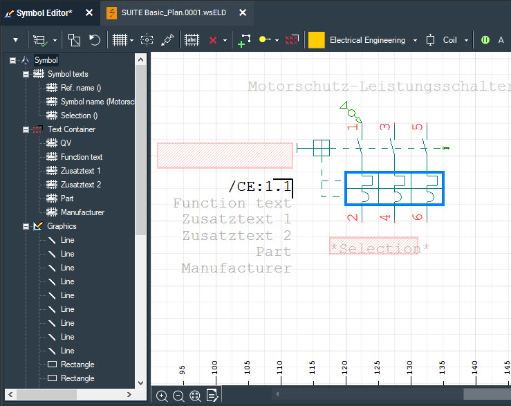
The colors of a symbol are stored in the symbol. You can change the color of the symbol yourself and, if available, also the ref. name and the symbol name.
As a rule, the symbol also contains a text container. If you change the color of the text container, you change the color for all elements contained there, e.g.:
- Cross-reference (color cannot be changed here)
- Function text
- Part
- Manufacturer
- Additional texts
- To load a symbol into the Symbol Editor, you have the following options:
- Click with the right mouse button on the symbol in the drawing sheet and select the context menu command Symbol Editor.
- Click with the right mouse button on the symbol in the Symbol Explorer and select the context menu command Symbol Editor.
- The symbol is displayed in the Symbol Editor.
- Click in the tree view on the left with the right mouse button on an element and select the context menu command Properties.
Note: You can also mark several elements.
- Change the color and, if necessary, the line width or text font size.
- Save your changes by opening the drop-down menu on the left in the toolbar and selecting the command Save.
The changes are saved in the symbol and thus in the library and will taken into account when you place the symbol again – even in other projects
Changing colors via the properties dialog
The colors of all elements except symbols can be changed via the properties dialog.
- Click with the right mouse button on the element and select the context menu command Properties. The properties dialog opens.
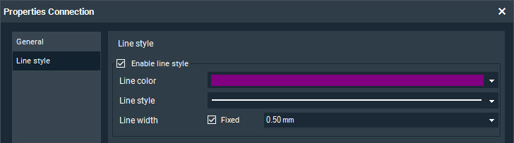
- Change the color and, if necessary, the line width or text font size.
- Close the dialog with OK.
Overriding the colors of elements
You can override the colors for many elements, e.g., generally for all symbols or for general texts.
To ensure that all symbols and texts have the same color, you can use the color override. This overrides the color information defined in the elements themselves globally, regardless of which color was defined in the symbol or for the text.
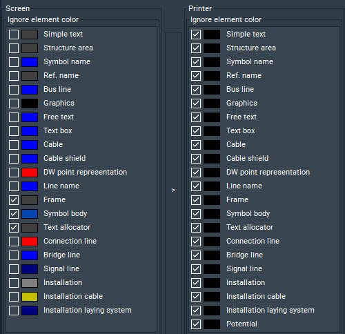
You can choose a different color override for the print output than for the on-screen display. By default, all elements are set to black (see area “Printer” on the right in the following screenshot). However, you can the transfer screen setting to the printer setting by using the arrow button between the selection windows. This prints the plan on a color printer or as a PDF as it appears on the screen. This printer setting is also used for the export to PDF.
Important: If you don’t want to output the potentials in black, you must manually disable the checkbox from the last entry in the “Printer” area on the right.
Overriding colors
- You can override the colors of elements in the schematic as well as the cabinet plan:
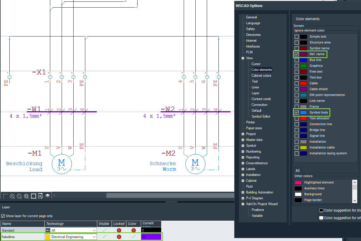
- To override the elements in the schematic, click on the menu command Tools | Settings (options) | View | Element colors.
- To override the elements in the cabinet plan, click on the menu command Tools | Settings (options) | View | Cabinet colors.
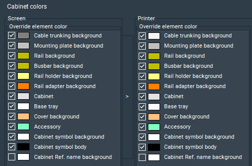
- Double-click on the color bar for the desired element and select the color. Confirm the dialog with OK.
- Select the check box in front of the element.
- Repeat steps 2 and 3 as needed for other elements.
- If you want to restore the default setting, click on the button Color suggestion for white background setting or Color suggestion for black background setting, depending on what background color is set.
Note: the reset default setting applies only to the screen setting, not the printer setting. - In the Other colors field, you can change the color for specific elements, such as cross-references or selected elements.
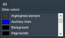
- Save your changes with OK.
All elements of the selected type are now overridden with the specified color. The changes are user-specific and thus also apply to all other projects.
Note
The element type “Symbol body” contains the symbol and additionally also the ref. name, a text container and the symbol name. You can subsequently override the ref. name and symbol name with a different color.
Color override with the layer function
The schematics and cabinet plans are composed of multiple “layers”. These layers are predefined according to their content (standard, cables, dimensions, etc.) and associated technology but can be modified to suit your needs at any time. You can also create additional layers.
If you now place a symbol on a specific layer and define a color for the layer, all the symbols on the layer will be assigned that color. You can thus easily change the color for these elements later.
If in the properties dialog of the opened project, the entry ON -> Create project-specific configuration is selected in the External configuration drop-down list, then the layer settings are project-specific and may thus differ from project to project.If OFF -> Delete project-specific configuration is selected in the open project instead, or if all projects are closed, then the layer settings are program-specific, i.e., affect all projects contained in the project management.
Notes
The layer colors also override the printer settings of the colors! If all printer settings are set to black (default), and some symbols on a layer are blue, the symbols are printed in the print preview, the PDF and on a color printer in blue, provided that Colored was selected in the print settings.
In the Symbol Editor, you can permanently change the assignment of the symbol to a layer.
Placing a single element on a layer
- Right-click on the element whose layer you want to change and select the context menu command Layer. The Select layer dialog opens.
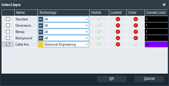
- Activate the row of the desired layer with a check mark.
- Click on the color bar for the layer and select the color. Confirm the dialog with OK.
- Activate the fields Visible and Color with a double-click. Activated fields are indicated with a green check mark.
- Save the settings with OK. The element is placed on the layer and marked with the color of the layer.
Placing multiple elements on one layer
- Activate the additional window “Layer” by clicking on the menu command View | Additional window | Layer and placing the additional window at a position of your choice.
- Click on the color bar for the desired layer and select the color. Confirm the dialog with OK.
- Activate the fields Visible and Color with a double-click. Activated fields are indicated with a green check mark.
- In the plan, select the elements to be placed on the layer.
- Click in the context menu of the selection on the command Properties.
- Select the desired layer under View | Layer and save with OK. The elements are placed on the layer and marked with the color of the layer.
Defining a new layer
- Click on the menu command Tools | Settings (options) | View | Layer.
- For clarity’s sake, first select the Technology filter. Only the layers already defined for the selected discipline are displayed.
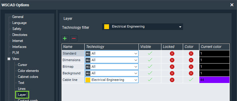
- Click on the Plus symbol button. A new custom layer is added.
- Click in the Name box and enter the name for the layer.
- Click on the color bar and select the color. Confirm with OK.
- Activate the fields Visible and Color with a double-click. Activated fields are indicated with a green check mark.
- If you want to create further layers, repeat steps 3 through 6.
- Save with OK.
I hope this blog post has helped you! For any questions regarding color control please contact our support team.
You can download this blog post here:
[button color=”extra-color-3″ hover_text_color_override=”#fff” size=”medium” url=”https://blog.wscad.com/wp-content/uploads/2019/09/Blog_Color_override.pdf” text=”PDF Download” color_override=”” image=”fa-play”]

Thomas Janowicz
Technical Writer,
Documentation Management