WSCAD SUITE X PLUS SP1 Overview
The WSCAD SUITE X PLUS offers you numerous innovations with the new Service Pack 1. The most important improvements and bug fixes are briefly presented here.
An overview of all new features can be found in the Online Help.
Multilingual PDF export
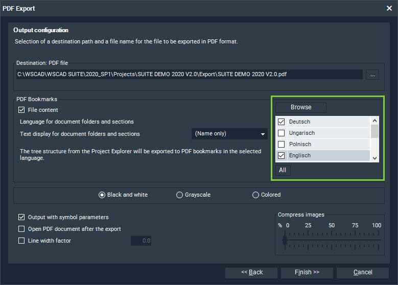
When exporting a project, a document folder or a single page to PDF, you can now create individual PDF files for all project languages in one step. The “PDF multilingual …” menu entry has been added to the export menu.
A PDF file is created in the export folder for each selected language, e.g.:
- SUITE DEMO_DE.pdf
- SUITE DEMO_EN.pdf
- SUITE DEMO_FR.pdf
Note: This function is only available with a valid maintenance contract.
.
Use of the path variables
You can use path variables in the directory path and file names when generating lists and plans, when backing up projects, when exporting to PDF/DXF/DWG/graphics and when exporting to the various production interfaces such as CadCabel, Komax and Steinhauer. The directory path and file name are then automatically created with the current values of the variables.
The following path variables are available:
| Path variable | Explanation |
|---|---|
| <Date> | Date, formatted as set, e.g., 12.09.2020 |
| <DrawingNumber> | Drawing number |
| <OrderNr> | Order number |
| <ProjectName> | Project name |
| <ProjectNumber> | Project number |
| <Time> | Current time, e.g., 16-49-13 |
The values of the path variables can be called up and changed via the properties dialog of the project (with the exception of the path variable <Time>).
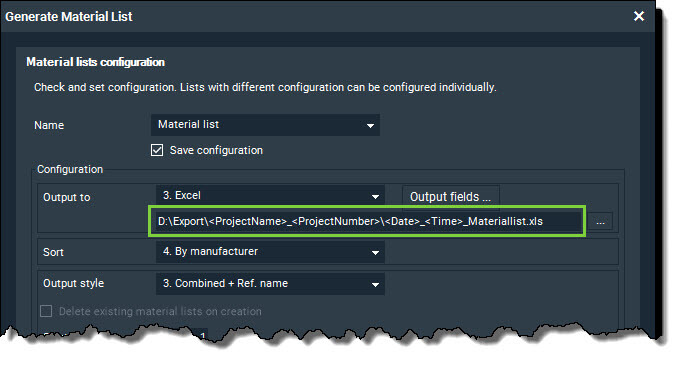
Example for the output of a material list
The path variables
<ProjectName>_<ProjectNumber>\<Date>_<Time>_Materiallist.xls
for example, become
SUITE DEMO 2020 V2.0_A123B456\12.09.20_16-49-13_Materiallist.xls
Further improvements and new features
Improvements for Building Automation
The following improvements have been implemented for the Building Automation discipline:
- The update of the data points and data point keys after changes to the data point database or the data point key plugin has been improved.
- Working with cables assigned to both EI and BA symbols has been improved in many places.
- The new data point key plugin BKS_15 is available via the Plugin Manager.
- When the data point key plugin BKS_13 is used, the structure identifiers are taken over correctly.
Interface to Phoenix PROJECT complete
The following import and export functions of the interface to Phoenix PROJECT complete have been improved:
- With the Phoenix PROJECT complete planning import of terminals, the mounting offset for the arrangement of the terminals on the rail is correctly taken into account.
- The Phoenix PROJECT complete planning export has been improved with regard to multi-level terminals and terminal accessories as well as wire jumpers and plug-in jumpers.
- The Phoenix PROJECT complete marking export has been improved with regard to references, PLC elements, terminals, cables and wires.
Interface to the Siemens TIA portal
The interface to the Siemens TIA portal has been expanded to include the following functions:
- The new tab, “Variable table” (Tag Table), was added in the PLC Manager. It contains the name, data type, channel address and comment of the channels of a PLC module.
- In the PLC Manager and in the properties dialog of a PLC parent element, the parent element can be defined as a CPU using a check box. Only one CPU per module is allowed.
- For the export of PLC elements, a data type such as Bool (standard), byte, int or real can be defined for each channel in the PLC manager via the new “Data type” field. During the import, the data type settings are read from the AML file and saved.
Interface to the PLM system PRO.FILE
A few small corrections and improvements have been made to the interface to the PRO.FILE PLM system. Parts that have received a part ID from PRO.FILE in WSCAD can be opened directly from the WSCAD part database in PRO.FILE. In addition, versioning with status check is also possible.
Further innovations
- When exporting to PDF, a new selection list allows you to choose whether sections and document folders should be displayed in the bookmarks menu tree of the PDF file with only the name, the name and description or the name and comment.
- Part management has been activated for the SUITE Compact version. In addition, the function “Edit contact comb” has been activated so that even combs can be taken over from a part.
- A new check box “Graphics and text are always in the foreground” has been added under “Tools | Settings (options) | Cabinet”. If it is activated, graphics and texts inserted on cabinet pages are automatically placed in the foreground. If the check box is deactivated, graphics and texts can now be placed in the background based on their settings in the properties dialog via “View | Display sequence | Back”.
- In order to display the parts of connection attributes in the material list, the radio button “Parts from connection attributes” was added to the “Generate material list” dialog.
- When importing a csv file into the part database, special characters such as umlauts are also supported. To do this, however, the csv files must be saved in UTF-8 format.
- The Update Dialog (accessible via “Help | Internet Update”) has been completely redesigned.
- With the new menu entry “Help | Delete empty containers”, all empty and borrowed expired containers are deleted.
Further bug fixes
- The navigation through the properties dialogs using the tab key has been improved.
- The export of CE pages to a JPG graphic has been improved. The texts in the placeholders of the frame are displayed correctly.
- In the connector chart, the connectors can also be displayed continuously over several columns arranged side by side per sheet.
- Creating new material in the Material Explorer works correctly.
- Creating a new project with the template “20. Sections with 4 aspects…” works correctly.
- After importing multi-level terminals via the “Import external material data” dialog of the Material Explorer, the multi-level terminals are correctly grouped and sorted in the Material Explorer.
- The structure identifiers of the elements from a placed macro are correctly displayed in the properties dialog of the symbols and in the associated managers.
- The texts of the connection attribute (wire color, wire cross-section, wire type, etc.) can be moved/rotated/modified separately.
- The wire information, e.g., length, cross-section and color are correctly output in the wiring diagram.
- The cursor is displayed correctly in the “Object” mode (can be set via “Tools | Settings (options) | View | Cursor”).
- The settings for the automatic redirection of doors can be changed under “Tools | Settings (options) | Installation”.
- If the check box “Part data from database” is deactivated when generating the material list, this data is not displayed for the list entries.
- After inserting a macro, the information from the part is correctly transferred to the connection attributes.
- In the material list, the component names of additional parts assigned to the contactors via the Contactor Manager are displayed correctly.
- When a PLC child element is placed, the text for the channel address is aligned correctly.
- The import of external files for automatic routing (accessible via “Tools | Cabinet | Import external wiring”) has been improved.
- In the Distribution and Circuit Manager, elements in the tree view can be moved by dragging and dropping – and elements that are on the same level can be sorted.
- In the “Change part” dialog of the part management, changes to the part number are correctly applied in the “Part” field.
- The description and comment of a structure area can be switched to visible and invisible correctly.
- If the “New symbol in document” function is called in the Material Explorer, a macro linked to the part data record is loaded correctly.
- The numbering type “Name sheet #1” set under “Tools | Settings (options) | Numbering | Reference” is applied correctly when creating new cables with the Cable Manager.
- Colors can be correctly assigned to the terminal pins in the Terminal Manager by using the “Terminal Pin Color Configuration” dialog.
I hope this blog has helped you. You can download this article free of charge.

Thomas Janowicz, Technical Writer
Documentation Management